Monthly Archives: October 2013
Waiting for components…
Actually, most of the components are in already. A small shipment from Mouser will arrive soon and I still have enough conductors to build 20 shields. More are on order and will here within 2-3 weeks. As with the ones needed for the prototypes I have not been able to find these at any source her in the US so I sourced them again from the UK through Allied Electronics / RS components.
I’ve also decided to invest in a laser-cut stainless steel stencil from Stencils Unlimited. The mylar stencil from Pololu.com was fine for the prototypes and likely would have lasted a good number of boards longer but the print quality of a stainless steel stencil is simply better and more consistent. Also of course a SS stencil is much more durable.
Another project I have been working on is a micro controller project with the aim to have “something” that can take advantage of the capabilities of this LED shield. One of the unique features of this shield is that it is controlled through the I2C bus. All components on the LED shiled (with the Exception of the temperature sensor) are FM+ capable. The FM+ specification allows I2C bus frequencies of up to 1MHz. Instead of 3mA FM+ components can drive 30mA, which allows much longer connections between I2C components. On the other hand most normal Arduino’s allow max 400KHz. So here is the Frankenduino I’ve described in a previous post:
It features an I2C bus extender based on the PCA9600 chip from NXP. I’ve successfully used a shield on 5 meters of CAT5 Ethernet cable and on my oscilloscope signals looked crisp even at 1.5MHz, so there is quite a bit of headroom to use even longer cables and more devices such as the shield.
Also, what can’t be seen on the Photo is a IR receiver and the Teensy3 happily receives and decodes IR signals from my Apple Aluminum remotes. A nice feature of the Apple remotes is that they can be paired to a device. I have not quite yet finished the code but I have determined the codes that the remote uses to be paired. However, before I do that I need to make a second prototype, which features an SD card slot for permanent data storage. It would not make much sense to having to re-pair a remote every time the micro controller has been powered down.
In order to function together with the I2C bus extender I also re-designed the little Arduino I2C extender board. It has SMD pads for different pull-up resistors and also needs a small Schottky diode when operated in conjunction with the PCA9600 I2C bus extender. Below is a picture of a “complete” system, including a micro controller, WiFi Ethernet Hub for remote control ability through OSC / TouchOSC and a LED shield with the I2C extension board. More shields can simply be daisy chained onto each other using inexpensive pre-configured CAT5 Ethernet cable.
Another interesting idea I had is that it could be quite useful to expose all the functions of the LED shield through the OSC protocol. That way you could create LED effects code directly from a computer e.g. with MaxMSP or Pure Data without having to program the micro controller.
Boards are in…
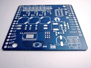
Yesterday I received the 100 boards I ordered from Hackvana.com. It’s a surprisingly small packet, mainly due to the fact that with 0.8mm these boards (for thermal performance reasons) are only half as thick as standard boards. The different thickness also did not cost any extra, it was actually a little less expensive. Most services I had checked before actually charge more for non-standard thicknesses.
Below is a photo of one of these. I focussed my point-&-shoot camera on a more intricate part of the board. Due to the shallow depth-of-field much else is rather unsharp, but enough can be seen to say that these are doggone gorgeous!
And, Yes, it’s been just two weeks since I ordered these. That’s pretty speedy if taking into account that these boards come from Shenzen/China!
On the other hand, due to the number of boards I chose DHL and not China-, or Hong Kong post.
100 PCBs are ordered!
A while ago I had done some more research on possible PCB manufacturing. Not the full assembly just the bare board. The difficulty was finding a source that had acceptable prices but at least offered 2oz copper.
Now I’ve placed an order of 100 pcs with hackvana.com after having a very fruitful email conversation and an IRC chat with Mitch who runs Hackvana. Ive read some very good reviews of the quality of these boards and am looking forward to receiving them. I will likely take 2-3 weeks as the actual manufacturing happens in Hong Kong.
Board specs are as follows:
- Blue Stop Mask
- White Silk Screen (top and bottom)
- RoHS finish (not ENIG)
- 2oz copper plated
- 0.8mm thick
- tab routed into single pieces
After a discussion with Mitch who runs Hackvana.com I decided not to get the immersion gold finish (ENIG) . Yes, it looks great on a bare board but on a populated board with tented vias there is nothing left visible of the gold plating. The real purpose for the ENIG finish is to have e very flat surface and a longer shelf life. The flatness of the boards will be fine for the intended purpose with the RoHS finish – no BGA chips in the design – and I don’t intend to have the bare board laying around for more than 3 months.
I also chose the 0.8mm thickness for better thermal performance as described in an earlier post. In fact and quite to my surprise, this was actually a little cheaper so there was no reason not do do it. I’ll post some pictures of the boards as soon as they have arrived.!


